Capitolo 8Chapter 8
Effetto FotoelettricoThe Photoelectric Effect
In questa scheda descriveremo un’esperienza relativa alla luce visibile. Dai risultati di questa esperienza scopriremo alcune importanti proprietà della luce che non sono comprese nell’ambito della teoria elettromagnetica, ma che possono essere spiegate solo introducendo dei concetti nuovi legati alla Fisica Quantistica.In this card we describe an experience concerning visible light. From its results we will discover some important properties of light that are not accounted for within electromagnetic theory, and that can be explained only by introducing new concepts linked to Quantum Physics.
Descrizione dell’esperimento.Description of the experiment.
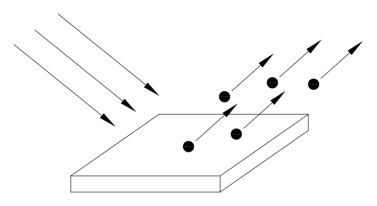
L’effetto fotoelettrico consiste nel fatto che quando la luce incide su una superficie metallica da questa vengono emessi degli elettroni (Fig. 1).The photoelectric effect consists in the fact that when light strikes a metal surface, electrons are emitted from it (Fig. 1).
Per rilevare questi elettroni si può usare un sistema come quello raffigurato in figura 2. Abbiamo un’ampolla di vetro nella quale è fatto il vuoto. All’interno dell’ampolla c’è un catodo con una superficie molto estesa, ed un anodo con una superficie ridotta al minimo. Quando la luce colpisce il catodo, questo emette elettroni per effetto fotoelettrico; alcuni di questi elettroni finiscono sull’anodo e formano una corrente I che può essere misurata.To detect these electrons one can use a system like the one shown in figure 2. We have a glass bulb in which a vacuum has been made. Inside the bulb there is a cathode with a very large surface, and an anode with a minimal surface. When light strikes the cathode, it emits electrons by the photoelectric effect; some of these electrons reach the anode and form a current I that can be measured.
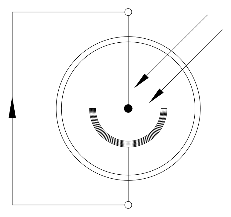
Anche l’anodo può emettere degli elettroni, tuttavia saranno molti di meno rispetto a quelli emessi dal catodo perché la superficie del catodo è molto più grande; inoltre il catodo e l’anodo non sono fatti dello stesso metallo. Infatti il primo è fatto di un metallo che libera elettroni molto facilmente, generalmente un metallo alcalino, mentre il secondo è fatto di un metallo che libera pochissimi elettroni, generalmente di platino.The anode too can emit electrons, but far fewer than those emitted by the cathode, because the cathode surface is much larger; moreover the cathode and the anode are not made of the same metal. Indeed the former is made of a metal that releases electrons very easily, generally an alkali metal, while the latter is made of a metal that releases very few electrons, generally platinum.
La corrente I che circola nel circuito dipende in generale dall’intensità e dalla frequenza della luce incidente. Questa corrente è molto debole e può essere misurata con un buon amplificatore di misura; tuttavia lo scopo del nostro esperimento non è quello di contare quanti elettroni vengono emessi, quindi non misureremo la corrente I.The current I that flows in the circuit depends in general on the intensity and on the frequency of the incident light. This current is very weak and can be measured with a good measuring amplifier; however, the aim of our experiment is not to count how many electrons are emitted, so we will not measure the current I.
Lo scopo dell’esperimento è di determinare con quanta energia vengono emessi i singoli elettroni, in funzione delle caratteristiche della luce incidente.The aim of the experiment is to determine with how much energy the individual electrons are emitted, as a function of the characteristics of the incident light.
Per misurare l’energia degli elettroni emessi si utilizza il sistema raffigurato in figura 3.To measure the energy of the emitted electrons we use the system shown in figure 3.
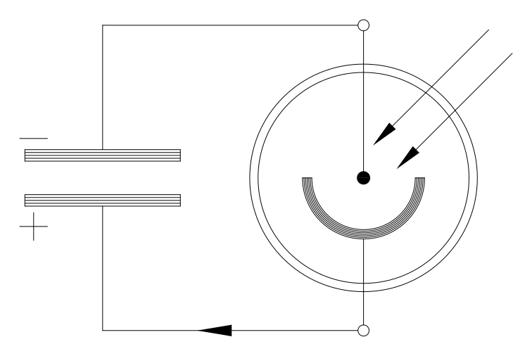
Quando si fa incidere la luce si ha un passaggio di elettroni e quindi il condensatore inizia a caricarsi. La tensione che si genera ai capi del condensatore produce un campo elettrico tra il catodo e l’anodo che si oppone al moto degli elettroni. Se l’energia posseduta dagli elettroni è sufficiente a superare la differenza di potenziale, allora il passaggio di corrente continua e il condensatore continua a caricarsi. Il processo si ferma quando la tensione ai capi del condensatore è tale che il prodotto  , dove
  è la carica dell’elettrone, è appena superiore all’energia
  posseduta dagli elettroni; infatti il prodotto
  è l’energia necessaria a superare la differenza di potenziale e, quando
  , avremo che gli elettroni, pur continuando ad essere emessi, non potranno più arrivare all’anodo.When light is made to strike, a passage of electrons occurs and so the capacitor begins to charge. The voltage that builds up across the capacitor produces an electric field between the cathode and the anode that opposes the motion of the electrons. If the energy possessed by the electrons is sufficient to overcome the potential difference, the current keeps flowing and the capacitor keeps charging. The process stops when the voltage across the capacitor is such that the product , where is the electron charge, is just greater than the energy possessed by the electrons; indeed the product is the energy needed to overcome the potential difference, and when , the electrons, although still being emitted, can no longer reach the anode.
Dunque per ottenere l’energia con la quale gli elettroni vengono emessi ci basterà misurare la tensione finale che raggiunge il condensatore ed usare la relazione Thus, to obtain the energy with which the electrons are emitted, it will be enough to measure the final voltage reached by the capacitor and use the relation  .
.
Descrizione dell’apparato sperimentale.Description of the experimental apparatus.
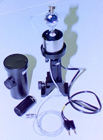
La figura 4 mostra una foto dell’ampolla che è stata usata per realizzare l’esperimento.Figure 4 shows a photograph of the bulb that was used to carry out the experiment.
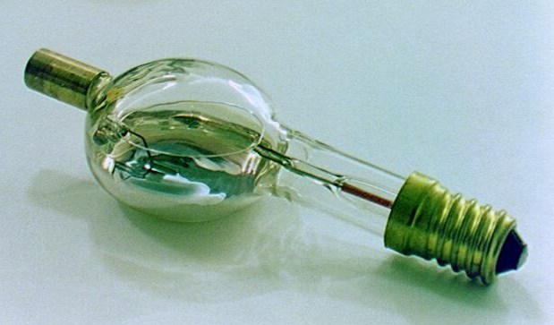
In questa ampolla il “fotocatodo” è costituito da uno strato di potassio (il potassio è un metallo alcalino) depositato direttamente sulla superficie interna del vetro, mentre l’anodo è costituito da un filamento di platino.In this bulb the “photocathode” consists of a layer of potassium (potassium is an alkali metal) deposited directly on the inner surface of the glass, while the anode consists of a platinum filament.
Visto che il potassio è molto “volatile” può capitare che un po’ del potassio che costituisce il catodo si possa trasferire e depositare sull’anodo di platino; in questo caso avremo l’effetto indesiderato che anche l’anodo potrà emettere elettroni. Per evitare questo inconveniente è stato preso un accorgimento: il filamento di platino può essere fatto attraversare da una corrente, in questo modo si riscalda e si purifica dagli atomi di potassio. Questa operazione di “pulizia” va eseguita prima di ogni prova sperimentale.Since potassium is very “volatile,” it can happen that some of the potassium forming the cathode transfers and deposits onto the platinum anode; in this case we would have the undesired effect that the anode too could emit electrons. To avoid this drawback a measure has been taken: a current can be passed through the platinum filament, so that it heats up and is purified of the potassium atoms. This “cleaning” operation must be carried out before every experimental trial.
L’ampolla viene montata su un apposito supporto rappresentato in figura 5; questo supporto è munito di un coperchio con una finestrella attraverso la quale viene fatta passare la luce.The bulb is mounted on a dedicated support shown in figure 5; this support has a lid with a small window through which the light is passed.
La figura 6 mostra una lampada ai vapori di mercurio utilizzata per illuminare il fotocatodo.Figure 6 shows a mercury-vapour lamp used to illuminate the photocathode.
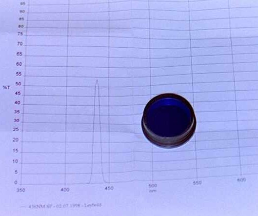
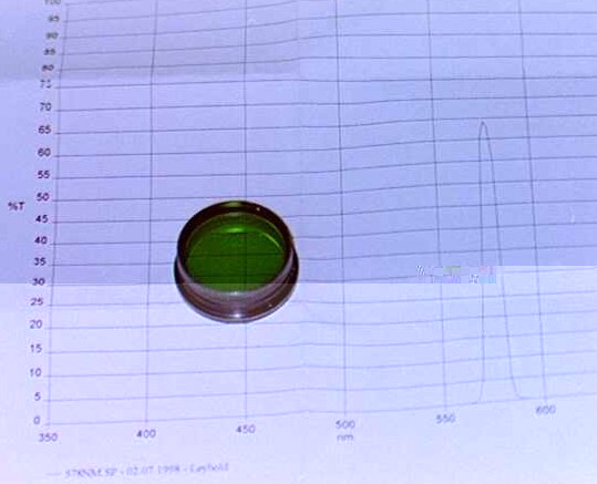
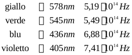
Per ottenere una luce monocromatica si usano dei filtri interferometrici; le figure 7 e 8 ci mostrano rispettivamente il filtro per il blu ed il filtro per il giallo. Useremo in tutto quattro filtri corrispondenti a quattro lunghezze d’onda, e quindi a quattro frequenze:To obtain monochromatic light, interference filters are used; figures 7 and 8 show, respectively, the filter for blue and the filter for yellow. We will use four filters in all, corresponding to four wavelengths, and therefore to four frequencies:
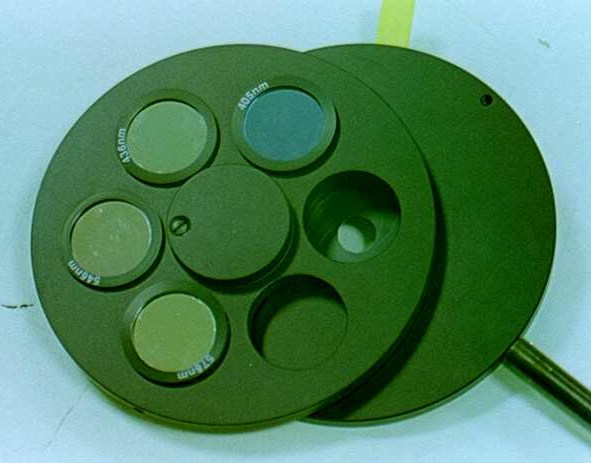
La figura 9 mostra il supporto per questi quattro filtri che comprende anche un diaframma ad iride. Ruotando il “cerchio” dei filtri si può selezionare un filtro e quindi si può regolare la lunghezza d’onda della luce incidente; invece aprendo e chiudendo il diaframma si può regolare l’intensità della luce incidente.Figure 9 shows the support for these four filters, which also includes an iris diaphragm. By rotating the filter “wheel” one can select a filter and thus adjust the wavelength of the incident light; by opening and closing the diaphragm, instead, one can adjust the intensity of the incident light.
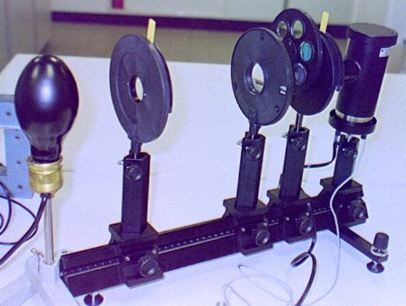
La figura 10 mostra il banco ottico montato; da sinistra a destra abbiamo: la lampada ai vapori di mercurio, un diaframma a iride, una lente convergente con una lunghezza focale di 50 mm, il supporto per i quattro filtri e per un altro diaframma a iride ed, infine, il supporto che contiene l’ampolla protetta dai raggi luminosi esterni.Figure 10 shows the optical bench assembled; from left to right we have: the mercury-vapour lamp, an iris diaphragm, a converging lens with a focal length of 50 mm, the support for the four filters and for another iris diaphragm and, finally, the support holding the bulb, shielded from external light rays.
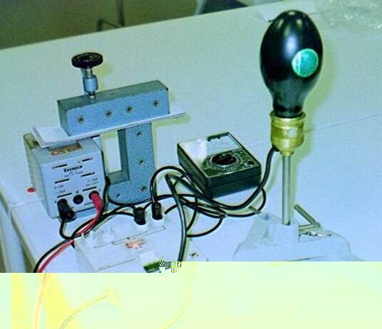
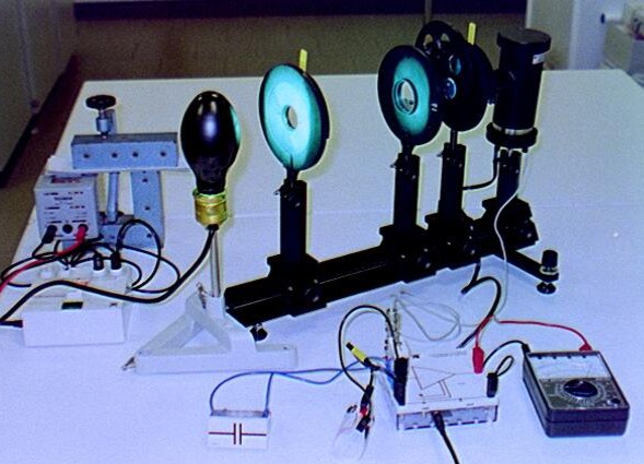
La figura 11 mostra l’intero apparato sperimentale mentre è in funzione. In basso vediamo gli strumenti di misura, a sinistra si vede il condensatore. Al centro c’è un separatore di impedenza e a destra un normale voltmetro.Figure 11 shows the entire experimental apparatus in operation. At the bottom we see the measuring instruments; on the left is the capacitor. In the centre there is an impedance buffer and on the right an ordinary voltmeter.
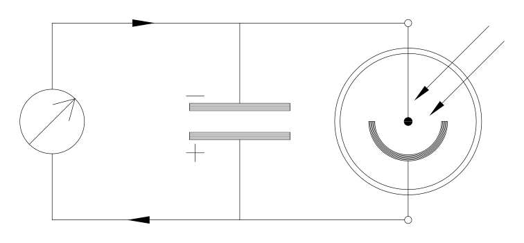
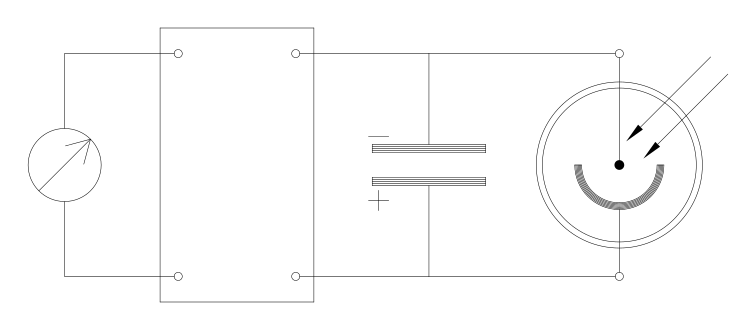
Per misurare la tensione ai capi del condensatore non può essere usato direttamente un normale voltmetro, perché l’impedenza interna di un voltmetro è troppo bassa e quindi costituisce una via di circolazione per la corrente fotoelettrica (Fig. 12). Per superare questa difficoltà si usa un separatore di impedenza come è schematizzato in figura 13. Il separatore di impedenza è uno strumento elettronico che ha un’impedenza interna dal lato del condensatore molto più alta dell’impedenza interna di un normale voltmetro, e che riporta in uscita la stessa tensione rilevata in ingresso, permettendo di eseguire la misura senza difficoltà.To measure the voltage across the capacitor, an ordinary voltmeter cannot be used directly, because the internal impedance of a voltmeter is too low and therefore provides a path for the photoelectric current (Fig. 12). To overcome this difficulty an impedance buffer is used, as sketched in figure 13. The impedance buffer is an electronic instrument that has a very high internal impedance on the capacitor side — much higher than that of an ordinary voltmeter — and that reproduces at its output the same voltage measured at its input, allowing the measurement to be made without difficulty.
Risultati sperimentali.Experimental results.
Prima di tutto si è osservato che l’energia di emissione degli elettroni non dipende dall’intensità della luce incidente. Infatti aumentando l’intensità della luce, regolando l’apposito diaframma a iride, si osservava che aumentava il tempo necessario per caricare il condensatore, il che significa che aumentava l’intensità della corrente, cioè il numero di elettroni emessi per unità di tempo; tuttavia la tensione finale che raggiungeva il condensatore restava invariata.First of all, it was observed that the emission energy of the electrons does not depend on the intensity of the incident light. Indeed, by increasing the light intensity — adjusting the dedicated iris diaphragm — the time needed to charge the capacitor was seen to increase, which means that the current increased, that is, the number of electrons emitted per unit time; nevertheless the final voltage reached by the capacitor remained unchanged.
Variando invece la frequenza della luce incidente si otteneva una variazione della tensione finale, e quindi una variazione dell’energia posseduta dagli elettroni emessi. La tabella seguente riporta i valori registrati dell’energia in funzione della frequenza della radiazione incidente.By varying the frequency of the incident light, instead, a variation of the final voltage was obtained, and hence a variation of the energy possessed by the emitted electrons. The table below reports the recorded values of the energy as a function of the frequency of the incident radiation.
| ColoreColour | FrequenzaFrequency (1014 Hz) | EnergiaEnergy (eV) |
|---|---|---|
| GialloYellow | 5,19 | 0,44 |
| VerdeGreen | 5,49 | 0,54 |
| BluBlue | 6,88 | 1,05 |
| ViolettoViolet | 7,41 | 1,24 |
Si osserva che i punti si dispongono su una retta con una pendenza di  ; si può osservare che cambiando l’ampolla con un’altra che contiene un metallo diverso, la pendenza della retta non varia quindi la pendenza della retta non dipende dal tipo di metallo; la pendenza ottenuta con misure più precise è di
  . Inoltre anche se non abbiamo eseguito le relative misure si può osservare che per frequenze minori di
  la tensione è zero, il che significa che non vengono emessi elettroni che possono caricare il condensatore; questa frequenza di soglia cambia se si cambia il metallo di cui è costituito il fotocatodo.One observes that the points lie on a straight line with a slope of ; one can note that changing the bulb for another containing a different metal does not change the slope of the line, so the slope does not depend on the type of metal; the slope obtained with more precise measurements is . Moreover, although we did not carry out the corresponding measurements, one can observe that for frequencies lower than the voltage is zero, which means that no electrons capable of charging the capacitor are emitted; this threshold frequency changes if the metal of which the photocathode is made is changed.
Interpretazione dei risultati.Interpretation of the results.
Questi risultati non possono essere spiegati in base alla teoria elettromagnetica classica. Infatti dal punto di vista classico l’energia di un’onda elettromagnetica non dipende in alcun modo dalla frequenza, ma dipende dal quadrato dell’ampiezza. Con il nostro esperimento invece abbiamo verificato che l’energia degli elettroni emessi non dipende dall’ampiezza dell’onda incidente, ma dipende dalla frequenza.These results cannot be explained on the basis of classical electromagnetic theory. Indeed, from the classical point of view the energy of an electromagnetic wave does not depend in any way on the frequency, but depends on the square of the amplitude. With our experiment, instead, we have verified that the energy of the emitted electrons does not depend on the amplitude of the incident wave, but depends on the frequency.
Il primo ad interpretare correttamente questi risultati fu Albert Einstein in un lavoro che presentò nel 1905, prima della formulazione della Meccanica Quantistica; per questo lavoro gli fu assegnato nel 1921 il premio Nobel per la fisica.The first to interpret these results correctly was Albert Einstein, in a work he presented in 1905, before the formulation of Quantum Mechanics; for this work he was awarded the Nobel Prize in Physics in 1921.
Einstein pensò che la luce fosse costituita da un fascio di particelle chiamate fotoni, e che ogni particella fosse dotata di una certa energia proporzionale alla frequenza  secondo la formula
  (dove h è la stessa costante di Planck che compare nell’equazione si Schrödinger!); in questa visione l’intensità della luce è proporzionale al numero di fotoni che passano per unità di tempo moltiplicato per l’energia posseduta da ogni singolo fotone.Einstein thought that light consisted of a beam of particles called photons, and that each particle carried a certain energy proportional to the frequency according to the formula (where h is the same Planck constant that appears in the Schrödinger equation!); in this view the intensity of the light is proportional to the number of photons passing per unit time, multiplied by the energy carried by each single photon.
Secondo quest’interpretazione quando un fotone urta un elettrone gli trasferisce la sua energia; l’elettrone a questo punto può superare la barriera di potenziale che lo lega al metallo ed, una volta fuori, avrà un’energia pari a quella fornitagli dal fotone  meno quella che ha dovuto spendere per superare la barriera di potenziale
  ; dunque uscirà con un’energia
  . Questa formula è in perfetto accordo con i risultati sperimentali. Se per caso la frequenza della luce è troppo bassa e si ha
  , allora l’elettrone pur avendo ricevuto l’energia dal fotone non ne avrà a sufficienza per superare la barriera di potenziale, e quindi non potrà essere emesso.According to this interpretation, when a photon strikes an electron it transfers its energy to it; the electron can then overcome the potential barrier that binds it to the metal and, once outside, will have an energy equal to that given to it by the photon minus the energy it had to spend to overcome the potential barrier ; thus it will emerge with an energy . This formula is in perfect agreement with the experimental results. If by chance the frequency of the light is too low and one has , then the electron, even though it has received the energy from the photon, will not have enough of it to overcome the potential barrier, and so cannot be emitted.
Il fotone è una particella che corre alla velocità della luce, quindi per poterlo studiare bisogna usare delle equazioni che siano coerenti con la Teoria della Relatività.The photon is a particle that travels at the speed of light, so to study it one must use equations that are consistent with the Theory of Relativity.
L’equazione di Schrödinger è stata formulata nella quarta scheda e l’abbiamo dedotta partendo dalla condizione che doveva essere coerente con l’equazione classica di Newton; ma questa equazione non è coerente con la Teoria della Relatività, quindi neanche l’equazione di Schrödinger è coerente con la Teoria della Relatività. Dunque, purtroppo, l’equazione di Schrödinger non può essere applicata al fotone.The Schrödinger equation was formulated in the fourth card, and we derived it starting from the condition that it had to be consistent with Newton’s classical equation; but that equation is not consistent with the Theory of Relativity, so neither is the Schrödinger equation. Therefore, unfortunately, the Schrödinger equation cannot be applied to the photon.
In futuro studieremo la Meccanica Quantistica Relativistica; per ora, come risultato di questa scheda, ci ricorderemo della relazione di Einstein per l’energia dei fotoni  .In the future we will study Relativistic Quantum Mechanics; for now, as the result of this card, we will keep in mind Einstein’s relation for the energy of photons .
Osservazione: nella Teoria della Relatività per ogni particella si può calcolare l’energia e la quantità di moto secondo le formule  e
e  . Per i fotoni abbiamo
  quindi:Remark: in the Theory of Relativity, for every particle one can compute the energy and the momentum according to the formulas and . For photons we have , therefore:
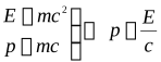
sostituendo per E la formula  abbiamosubstituting the formula for E, we have
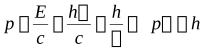
Dunque abbiamo ritrovato la relazione di De Broglie anche per i fotoni.Thus we have recovered the De Broglie relation for photons as well.