Chapter 3
Experiments with Electrons
Every material object, as we know, is made up of an aggregate of elementary particles; one of the most important particles is the electron, because it determines many properties of matter. In this card we will describe some experiments by which it is possible to isolate the electron and study its fundamental properties.
First experiment: conduction of current in a vacuum

Fig. 1 shows a glass bulb in which a vacuum has been made. Inside the bulb two electrodes A and B are arranged; electrode A can be heated by the Joule effect. If a voltage is applied between points A and B (fig. 2), a flow of current is observed, which can be detected with an ammeter connected in series with the circuit. If electrode A is heated, the current is seen to increase appreciably.

How can current flow between two electrodes separated by vacuum?
The phenomenon can be interpreted by imagining that there exist charged particles that can move through the space between the two electrodes. When a potential difference is applied, electrode A emits these charged particles which, moving to the other electrode, form the current in the vacuum. When electrode A is heated, it releases a greater number of particles and therefore allows a greater flow of current.
▶Try the interactive simulator · Current in a vacuum→
A gun of charged particles (the electron gun)

The device shown in figure 3 is an ingenious system that allows us to produce a focused beam of negatively charged particles.
Consider a negatively charged particle emitted by the hot filament A. Along the path A→B the particle is slowed by a potential difference of about 10 V; this stage serves to regulate the flow of particles: the higher the voltage, the fewer particles pass to the next stage. Along the path B→C the particles are accelerated considerably by a potential difference of the order of 5000 V; this stage serves to give energy to the particles of the beam. Along the paths C→D and D→E the particles are first slowed and then accelerated by a potential difference of the order of 100 V. These two stages constitute two electrostatic lenses, the first converging and the second diverging, which allow the beam to be focused at a certain fixed distance.
At the output of this system one obtains a beam of fast, well-focused negatively charged particles.
It is clear that a gun of charged particles can be made in many different ways, and that it can have an accelerating voltage much higher or much lower than 5000 V; however, the simple scheme we have shown is sufficient for the experiments we will describe in this card.
It is interesting to try powering the system with voltages of the opposite sign. In principle we should obtain a gun of positively charged particles, but one observes that no particle is projected. This can be explained by supposing that a heated filament emits only negatively charged particles.
Phosphor screen

The beam of charged particles is not directly visible. To detect the beam a phosphor screen is used (fig. 4).
The phosphor screen is essentially a glass plate on which a particular chemical substance is deposited that, when struck by the accelerated charged particles, emits visible light, making the point of incidence luminous.
For now we will not concern ourselves with explaining this phenomenon of phosphorescence, but will use it only as an empirical fact that allows us to carry out our experiments.
Deflection of the beam by electric and magnetic fields

The apparatus in figure 5 consists of an electron gun, a pair of plates that allow us to produce a uniform electric field, and a phosphor screen. Everything is enclosed in a glass chamber in which a vacuum has been made. If the plates are powered with a potential difference, a deflection due to the electric field is observed, exactly as we expected on the assumption that the beam was formed by a set of negatively charged particles. This experiment therefore confirms the hypothesis that a heated conducting filament emits negatively charged particles.

In the system of figure 6 the two conducting plates have been replaced by two coils. By passing a current through these coils, a magnetic field is generated that causes a deflection of the beam. In this case too the deflection is the one we expected on the hypothesis that the beam is composed of charged particles.
Now let us compute the deflection angles and relative to the electric field and to the magnetic field, on the assumption that Newton's laws are valid.
Deflection due to the electric field

Deflection due to the magnetic field

As can be seen from the formulas, the deflection angles depend directly on the ratio between the charge and the mass of the charged particles. If the beam were composed of different types of particle, with different ratios , then we would obtain different deflection angles for the different particles, and we would observe more than one bright spot on the phosphor screen. The fact that we obtain a single deflection angle is proof that the particles emitted by the incandescent filament all have the same charge-to-mass ratio. It is very reasonable to think that they are in fact a single type of particle, with a definite mass and a definite charge. This hypothesis is confirmed by many other experiences, and the particles in question are called electrons.
Thomson's experiment
The device for Thomson's experiment contains both deflection systems: the plates for the electric field and the coils for the magnetic field.
The aim of the experiment is to determine the ratio between the charge and the mass of the electron, and it is carried out in two steps.
First the two systems are powered in opposition, adjusting the intensities of the electric and magnetic fields so as to observe zero deflection. In this way there is a balance between the magnetic force and the electric force and, from the corresponding equilibrium relation, the speed of the electrons can be obtained:
Then the deflection due to only one of the two systems is measured and, knowing the speed , the ratio is determined. For example, by measuring :
With these experiments we have identified an important particle with negative charge, the electron. However, we have not yet observed any positive particle: this is because a heated filament emits only electrons, and so the electron gun cannot fire positively charged particles. But we know that matter is essentially neutral, so for every negative charge there must be a corresponding positive charge. In the next experiment we will show that a neutral atom is made up of a certain number of electrons and a positive particle. The positive particles obtained by removing one or more electrons from a neutral atom are called positive ions.
▶Try the interactive simulator · Deflection and e/m ratio→
Separating the atom into positive ions and electrons

Figure 7 shows the experimental apparatus. We have a glass tube and, at the right and left ends, two phosphor screens. In the central part two perforated electrodes are arranged. Inside the tube there is a certain gas at low pressure (about atmospheres).
If we power the two electrodes with a voltage of about 1000 V, two bright spots appear on the two screens (fig. 8): on the right we obtain a beam of negative particles, on the left a beam of positive particles.

We can insert deflection systems to study the kind of particles that are projected, measuring their charge-to-mass ratio (fig. 9).

Carrying out these measurements, one observes that the negative particles do not depend on the type of gas introduced into the apparatus, and are the same ones we found with the electron gun: so they are electrons. The positive particles, instead, depend on the type of gas. One also observes that the positive particles undergo a much smaller deflection than that undergone by the electrons under the same electric field. This means that the ratio of the positive particles is much smaller than that of the electrons.

In some cases, as figure 10 shows, the positive particles produce two or even more bright spots. The additional spots correspond to a ratio that is a multiple of the main one: , , etc.
This experiment can be interpreted by imagining that atoms are formed by a positive particle, which we will call an ion, and a certain number of electrons. Most atoms are joined together and form a neutral structure. In some cases, however, there can also be split atoms and, when a voltage is applied to the electrodes, the ion and the electrons are accelerated in opposite directions. In this way, beyond the holes made in the electrodes, beams of charged particles are generated.
The positive particles undergo a much smaller deflection than the electrons; therefore, since they must have the same charge , this means that they have a much larger mass . The ratio between the electron mass and the ion mass depends on the atom considered and is of the order of .
The fact that ions can produce more than one bright spot is explained by the fact that an ion can also be obtained by removing more than one electron from a neutral atom. In this way the charge of the ion becomes a multiple of that of the electron, while the mass remains practically unchanged (because the electron is very light compared with the neutral atom, so removing one electron does not change the mass much); the result is a ratio that is a multiple of the fundamental one and a multiple deflection.
At this point a question may arise: how many electrons can be removed from a neutral atom?
Some experiments, which we will not discuss in this card, show that atoms are made up of a finite number of electrons. This number depends on the type of atom; it can be just one, as in the case of hydrogen, and can exceed one hundred. The positive particle that remains when all its electrons are removed from an atom is called the nucleus.
So far we have measured the ratios of the electrons and of the ions, but we have not yet measured the charge and the mass separately. To conclude this card we describe a very ingenious and elegant experiment that allows us to measure the charge of the electron.
Millikan's experiment
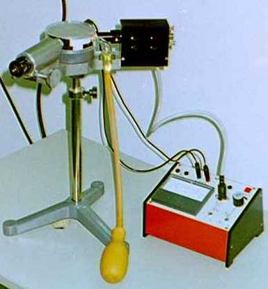
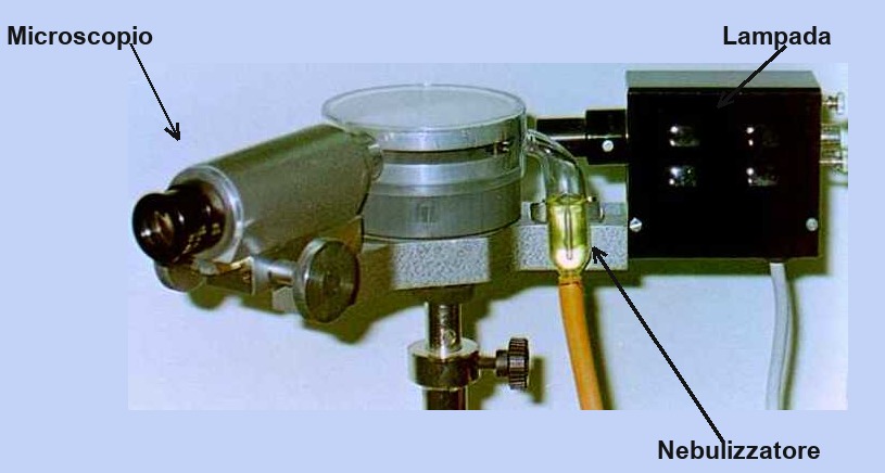
Figures 11 and 12 show two photographs of the apparatus.

The first element to observe is the Venturi-effect oil atomiser, shown schematically in figure 13. The droplets sprayed by the atomiser enter through two small holes between the conducting plates of a capacitor enclosed under a transparent plastic chamber; figure 14 shows a diagram of the atomiser, the capacitor and the droplets.

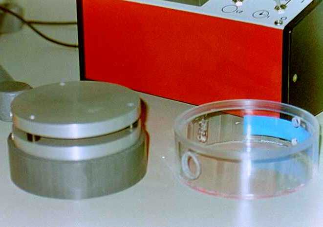
Figure 15 shows a photograph of the capacitor and the chamber enclosing it. The droplets sprayed inside the capacitor are visible through a microscope, shown on the left in figure 12; the illumination of the inside of the capacitor is provided by a lamp shown on the right in the same figure 12. The photograph in figure 16 shows what one sees looking through the microscope.
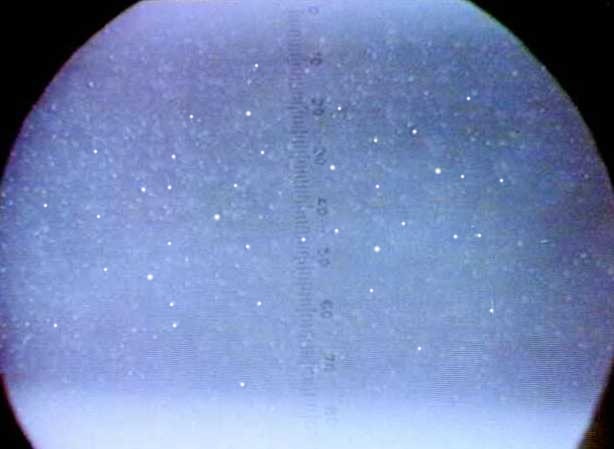
Observing the droplets, one sees that they fall under the action of the gravitational field (actually they are seen to rise because the microscope inverts the image).

If the plates are powered with a certain voltage (fig. 17), one observes that the motion of some droplets changes: some fall faster, some fall more slowly, some others begin to rise. This means that some droplets carry a non-zero electric charge, and therefore experience a force under the action of the electric field.
The aim of the experiment is to measure the charge of one of the droplets. By adjusting the voltage one can make the chosen droplet stay still in equilibrium. In this condition we have a balance among the various forces: the weight, the Archimedean buoyancy due to the air, and the electric force:
In this equation is the acceleration of gravity, and are the densities of the oil and of the air, is the radius of the droplet and is the electric field present between the capacitor plates. These quantities are all known, except the radius of the droplet; therefore, to derive the charge , we must find a way to measure this radius. The method devised by Millikan is very clever.
The electric field is switched off and the droplet begins to fall. The falling speed of the droplet increases until it reaches a limiting speed at which the forces due to the weight, the Archimedean buoyancy and the viscous friction with the air balance:
In this equation we have used Stokes' formula for the viscous force, , where is the viscosity of the air and is the speed of the droplet.
From the second equation we can obtain the radius of the droplet:
Now we can obtain the charge from the first equation:
substituting the formula found for :
The final formula for the charge is
The quantities to be measured in performing the experiment are the electric field and the falling speed of the droplet . The field is given by the ratio between the applied voltage and the distance between the capacitor plates. The speed is obtained from the ratio between the distance and the time . The distance is measured with a graduated scale visible inside the eyepiece; the time is measured with a manual stopwatch.
Experimental results
The constants to be used in the formula for the charge are:
Substituting these values we obtain the formula
The following table shows some sample measurements.
| V (Volt) | Δx (10-3 m) | Δt (s) | q (10-19 C) |
|---|---|---|---|
| 140 | 3.2 | 45.4 | 8.3 |
| 50 | 3.2 | 125.5 | 5.1 |
| 250 | 3.2 | 59.1 | 3.2 |
| 480 | 3.7 | 24.1 | 8.0 |
| 400 | 3.7 | 49.5 | 3.3 |
| 510 | 3.7 | 41.7 | 3.3 |
| 270 | 3.2 | 88.1 | 1.6 |
| 380 | 3.2 | 44.1 | 3.2 |
| 400 | 3.2 | 66.1 | 1.7 |
The following histogram represents a series of 50 measurements.

The important thing to notice in these results is that the values of the charge are not random. The value of about C appears repeatedly, and then other values appear that are multiples of C, namely C, C and C. Moreover, there are no values smaller than C.
These results prove that the charge accumulated on the oil droplets is corpuscular, that is, it is made up of a certain number of elementary particles, each of which carries a constant charge of C.
That these particles are electrons is not a forced consequence of the measurements: it is a conjecture, though one that the agreement between independent experiments makes hard to avoid. The carriers that charge the droplets are negative and elementary; identifying them with the particles emitted by the incandescent filament, the charge-to-mass ratio measured in Thomson's experiment gives them a mass thousands of times smaller than that of an atom — too small for an ion, and consistent with what we observed when separating ions and electrons. Once this identification is accepted, Millikan's experiment gives us the charge of the electron.
▶Try the interactive simulator · Millikan's experiment→
Summary
In this card we have become familiar with an important elementary particle, the electron. We have described experiments in which the electron behaves like a material particle of classical mechanics. Through these experiments we have seen how the ratio between charge and mass can be measured and, finally, thanks to Millikan's experiment, we have measured the charge C. We have also described an experiment that allows us to gather the first information about the structure of the atom: we have seen that an atom is a neutral system made of a positive nucleus and a certain number of electrons, and we have observed that a nucleus is much heavier than an electron, so it contains almost all the mass of the atom.